 A Word Clock is a clock that tells the time using words.
In an era when super-accurate digital clocks are available to most people on the planet, it intrigues me that Word Clocks have a place as they only show the time to the nearest five minutes!
Building one has been on my project to-do list for a while, but I didn’t want to invest the time and money needed for the various ‘from scratch’ build projects that I found online.
My inspiration for this project comes from the Adafruit website, where an 8×8 neopixel matrix is used to create a colorful Word Clock. It seemed to me that I could build a mini version using 8×8 monochrome LED matrix run by a MAX7219 IC. The challenge I set myself was making it as small as I could.
The Word Matrix
The word matrix is the main ‘display’ for a word clock and is the starting point for the design, as everything else fits around that. Fortunately the hard work of creating the word matrix for an 8×8 format was done by Adafruit for their project. As you would expect, having a limited number of LEDs means there need to be compromises compared to the larger word clocks, with some words split up. In
this implementation, the mask is in 3 sections – the top 3 lines for
minutes, line 4 for past/to text, and the last 4 lines for the hour. A
plan for how the words are built up is shown on the right (click to
enlarge). Alternatives for some words are highlighted in green.
In
this implementation, the mask is in 3 sections – the top 3 lines for
minutes, line 4 for past/to text, and the last 4 lines for the hour. A
plan for how the words are built up is shown on the right (click to
enlarge). Alternatives for some words are highlighted in green.Each letter of the mask is aligned over one of the LEDs of the matrix. I created an appropriately sized WordClock Text Mask using Microsoft Word. The idea was to print the mask on paper and cover the LED matrix. Testing confirmed this would work, with the LEDs able to shine through the paper. As a bonus, the paper also acted as a very satisfactory light diffuser.
System Hardware
Once I was sure that the concept was valid, it was time to consider the system architecture.

Finally, a momentarily-on switch is used for setting and displaying the time, and the project is powered through a USB socket.
The hardware was prototyped using available existing modules and an Arduino Uno, shown below.

Software
The software for this project is available from my library site. Essentially it does 4 things:- Periodically update the display.
- Display the time as digits when the mode switch is pressed.
- Manage time setup when the mode switch is double pressed.
- Manage Summer Time offset when the mode switch is long pressed.
- In order to keep things flexible, each word is mapped in a data table, used to turn on the correct LEDs in the matrix. Changing what is displayed is a matter of changing the data table rather than any code.
- To get to the nearest 5 minutes, each five minute interval encompasses 2 minutes before and 2 minutes after the actual 5 minute mark (eg, 5 past the hour is 3 past until 7 past).
- Once we are beyond the half hour, the hour needs to be incremented for a word clock (ie, 1:35 is twenty five to two).

Actual Time. It is sometimes useful to know the real time! Pressing the mode switch once displays the time in digits on the LEDs, two digits for the hours followed by 2 digits for the minutes. The digits are a small number font defined in the code, where each digit is 3 LEDs wide and 7 high, with one blank column. At 4 columns total width, two digits can be displayed across the 8 columns of the LED matrix.
Time Setup. The time needs to be set up somehow. This is accomplished by double pressing the mode button. At first the hours are displayed as 2 digits and single presses (or auto repeat, as I am using the MD_KeySwitch library) of the mode button will increment the hour with wraparound. Once the hours are set a double press moves to editing the minutes in a similar manner. Another double press completes the editing and returns to the word display. A 10 second inactivity timeout prevents the display from remaining in edit mode indefinitely.
Summer Time Offset. Rather than change the clock time for the Summer Time period, a long press of the mode switch will set up an automatic +1 hour offset when displaying the current time. Summer Time offset is reset to 0 by another long press. The display will show a ‘+1’ or a ‘+0’ to inform which mode it is in. The current Summer Time mode is stored in EEPROM.
The Clock Case
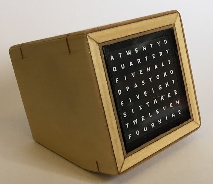
I wanted the unit to sit on a desk and look like a small old-style computer monitor, so I built a small case to suit. To keep the unit as small as possible, the case was proportioned around the size of the LED matrix.
The front ‘screen’ is a small square of perspex (acrylic) cut to fit the front opening. The size of the window is slightly larger than the LED matrix and the border was sprayed black after masking off the central area.
The inside of the case is painted black to minimize any stray light in the closed box. The outside is finished in a citrus based woodworking oil (smells great!).
Putting it all together


All wires were then soldered to the Pro Mini and it was hot glued to the base of the back. The LED SPI connection was then plugged in and the entire unit tested before finally closing the case.
Note: Text updated April 2017 for Summer Time offset upgrade.


