I recently obtained a couple of these sensors for a project and have been exploring how they can be used to detected both DC and AC currents. I also wanted to understand what was needed for proper calibration of the ADC readings at the Arduino.
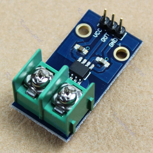
The ACS712 hall effect current sensor is commonly available from generic suppliers incorporated onto GY712 sensor boards shown in picture.
A full sketch with all the code presented in this article can be found at my libraries site.
Using the Sensor

The sensor consists of a linear Hall circuit with a copper conduction path located near the surface of the chip. Applied current flowing through the copper conduction path generates a magnetic field which the sensor converts into a linearly proportional voltage ±2.5V centered around 2.5V. This voltage is read through the Arduino ADC as a 10 bit number (0-1023), from which the DC or AC current can be calculated.
The voltage returned by the sensor depends on the sensor’s rating. The ±5A sensor will output 185mV for each amp (mV/A), the ±20A 100mV/A and the ±30A 66mV/A. Accurately knowing the voltage is therefore pretty important!
Calibrating Sensor Readings
The ACS712 datasheet states that the sensor is “factory-trimmed for accuracy”. This presumably guarantees that the output will be linear.For a straight line y=mx+b, the linear output (y) needs to be calibrated for zero (b) and for the slope (m) of the line.

The zero adjust is simply the offset from true zero when there is no current flowing through the sensor. Nominally this will be 2.5V, read as the central point of the 0-1023 ADC range (512). A simple way to determine the zero adjust is to take a few readings and average the deviation from 512. This is easiest to do once in the setup() function.
 // Read the analog input a few times to makes sure that we get
 // a good zero adjustment from nominal center value. There should be no
 // current flowing while this is happening.
 for (uint8_t i=0; i<10; i++)
 {
   uint16_t error = 512 - analogRead(SENSOR_PIN);
   sensorZeroAdj = ((sensorZeroAdj * (i-1)) + error)/i;
 }
The slope of the line is fixed by the sensor conversion factor (mV/A) but what needs calibration are the ADC values on the x axis. The ADC returns 0 for 0V and 1023 when the input reaches the Arduino supply voltage Vcc (that is, a scaling from 0 through Vcc). Vcc
is nominally 5V but in practice it will vary depending on the source of
supply and what else is being powered by the Arduino board. Simply
assuming Vcc = 5V is inaccurate and becomes more so at the higher end of the range.To get around this, the Arduino can be calibrated against a stable 1.1V internal reference voltage. This is discussed in many other places (for an example, look here). Using the actual Vcc ensures the accuracy of the resulting conversion.
Sensing DC Current
DC current flows in the same direction over time, so sensing the current is simply a matter of reading the analog value, applying the calibration parameters, and scaling to the obtain the current reading.For computational efficiency integer arithmetic is used throughout in the code below. To retain significant digits, the value is calculated in milliamps rather than amps.
const uint8_t SENS = 100; // sensor value from datasheet in mV/A

int32_t senseCurrent(void)
{
  int32_t sensorValue = analogRead(SENSOR_PIN) + sensorZeroAdj;
  int32_t Vcc = readVcc();

  int32_t convertedmA = (1000L * (((Vcc*sensorValue)/1024L)-(Vcc/2)))/SENS;

  return(convertedmA);
}
Sensing AC Current
Sensing AC current is slightly more complex
as the current reverses direction with each sinusoidal cycle. What we
are generally interested in is the Root Mean Square (RMS) voltage Vrms (see RMS voltage of a Sine Wave for a tutorial on this concept).
Vrms can be calculated from the peak voltage Vp of the sine wave as Vrms = Vp ⁄ √2.
Using the Arduino, we can repeatedly sample the voltage to get the
highest reading. As the sine wave has a know frequency (50 or 60Hz),
sampling for two wave periods should be sufficient. To get better
accuracy, the code below samples for both maximum and minimum, with Vp half the difference between the two.
const uint8_t AC_FREQUENCY = 50; // in Hz
const uint8_t SENS = 100; // sensor value from datasheet in mV/A

int32_t senseCurrent(void)
{
  const uint8_t timeSampling = 2 * (1000 / AC_FREQUENCY);

  int32_t convertedmA;
  uint16_t sampleMin = 1024, sampleMax = 0;
  int32_t Vpp, Vcc = readVcc(); // both in milliVolts

  // Collect samples over the time sampling period and
  // work out the min/max readings for the waveform
  for (uint32_t timeStart = millis(); millis() - timeStart < timeSampling; )   {     int16_t sensorValue = analogRead(SENSOR_PIN) + sensorZeroAdj;       if (sensorValue > sampleMax) sampleMax = sensorValue;
    if (sensorValue < sampleMin) sampleMin = sensorValue;
  }

  // now calculate the current
  Vpp = (((sampleMax-sampleMin)/2)*Vcc)/1024L;
  convertedmA = (707L * Vpp)/SENS; // 1/srt(2) = 0.7071 = 707.1/1000

  return(convertedmA);
}


